USB3: why it's a bit harder than USB2
A few people on twitter have asked me to explain why the USB3 winds up being much harder to implement than USB2.
The answer is more than will fit in a single tweet, so I thought I'd put a quick-but-rough answer, here. This is
by no means comprehensive; consider it a longer tweet what a tweet would be given I had more than 240 characters and a proclivity to babble. (I do.)
A lot of the challenges come from the way we work around physical-layer limitations. Put poetically, physics gives us lots of little obstacles we have to work around in order to talk at 5 billion transfers per second (5GT/s).
It's hard to establish common “DC operating conditions” on both sides of a link.
It's not trivial to get the same bias voltages – and common grounds – across a long motherboard or down a cable – and when you're operating at really high frequencies, you're a lot more sensitive to changes in your operating environment. In USB3, we work around this by capacitively isolating both sides of the link from each other – in short, we use capacitors to ensure only signal changes are carried across the link, which means that both sides can establish their own local operating conditions.
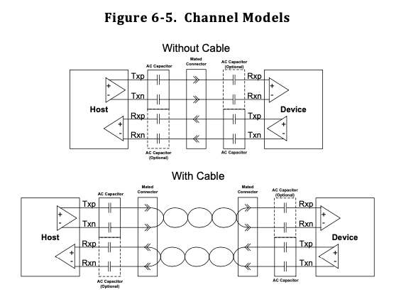
From the USB3.2 specification: diagram showing how signals are isolated
This puts some requirements on the digital protocols used to exchange data. Because data currents are exchanged as the relevant capacitors charge and discharge, capacitive coupling only works when those capacitors have room to charge and discharge. This means our data must be DC-balanced; we have to spend as much time charging those capacitors as we do discharging them. In digital terms, this means we have to encode the data in a way that sends the same amount of 1s and 0s.
It's hard to establish a “common clock” across both sides of a link.
When sending serial data, you typically have two challenges: you need to make sure both sides are sampling the data at the same rate, and that both sample clocks are synchronized enough that you're sampling at the right point. Many high-speed protocols deal with this using a technique called clock recovery, which essentially means that each receiver looks at the data it receives and tries to figure out what the clock that produced it looks like.
If both sides have agreed on a clock rate, this can be simple, in theory: if the receiver sees a change in its received data, it can infer that that changed happened on an active edge of the transmitter's clock, and so it can start to figure out how to align its internal clock with the transmitter's.
This introduces another protocol requirement: for clock recovery to work, the data has to change frequently enough that the two sides can keep synchronized. At 5GT/s and high data throughputs, there's not much time for clocks to become synchronized when a packet is received; accordingly, it's important that data is encoded with lots of transitions, even when the line is idle.
To ensure both DC-Balance and sufficient transition density, USB3 uses a method of encoding called 8b10b encoding. In this encoding scheme, every single byte of data is transmitted as ten bits, with encodings chosen so that:
- A typical data byte can be transmitted either as a code with one more one than zero, or one more zero than one. This allows the transmitter to choose between the two encodings, in order to keep the data stream at 50% ones.
- Every valid encoding has sufficient transition density to ensure that it's useful for clock recovery.
I won't go into more 8b10b background here, but you can read about the typical IBM implementation on wikipedia.
It's hard to run both sides of the link at the same clock rate.
Even with successful clock recovery, it's difficult to have both sides of the link produce and consume data at the same rate. Each side's internal logic is running off of its own clock source; and every clock has a bit of deviation from its nominal frequency. For the protocol to function despite these differences, the USB3 specification allows each clock to deviate from its nominal value by up to a certain tolerance; and specifies a method for compensating for this tolerance. This technique is appropriately named clock tolerance compensation, or CTC.
To compensate for mismatches in sender/receiver clock rates, USB3 requires senders to periodically insert filler data into their transmitted data-stream. Receivers can then discard this data; allowing a brief pause in which the slower side of the link can “catch up”. For this to be useful, the filler data (called ‘skip sets’) must be sent regularly; which means additional logic on the transmitter side for insertion, and additional logic on the receiver side for removal.
It's hard to deal with varying electrical properties of different transmitters, receivers, and cables.
When operating at very high frequencies, all of the little non-idealities along your transmission path really add up. At slower data rates, there's plenty of time for digital signals to “settle” after a change; making the non-ideal properties of your transmission lines less important. The faster your data gets, the more important it is for your data to reach a “readable” value quickly.
To help with this, most high-speed receivers employ a technique called receiver equalization, which uses analog hardware to help reshape signal transitions, so they can be more reliably sampled. Equalization helps to “cancel out” some of the ways the non-ideal transmission path adversely affects the signal.
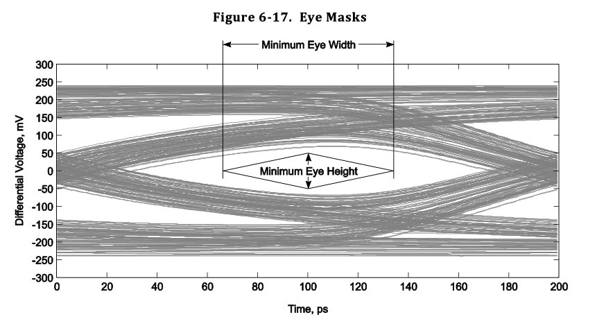
From the USB3.2 specification: an 'eye diagram', which shows an overlay of many rising and falling transitions, illustrating how non-ideal properties affect the link.
Since every transmission path is different – due to different transmitter, receiver, and cable properties – it's impossible to create a single “one size fits all” equalizer. Instead, each USB3 equalizer needs to be tuned to its transmission path via a process called link training.
At the start of each USB3 communication, link partners repeatedly exchange collections of known data called training sets, which give the opportunity for each side to tune their equalizer. Training sets include both sets of data chosen to have high transition density and sets designed to include a wide range of “normally-distributed” data.
During a few milliseconds of data exchange – an eternity in fast-protocol terms – both sides of the link gradually tweak their equalizer settings until they're clearly seeing the expected values from the other side.
It's hard not to generate harmful interference.
USB3 has a very high transition rate – it easily qualifies as high radio-frequency signaling – and its link often tends to exchange repeating data. This has a nasty side effect: even a well-functioning link can act as an antenna; unintentionally emitting RF that can interfere with nearby systems. The more repeating elements this signaling has, the more troublesome the interference tends to be.
To reduce the amount of harmful interference generated, USB3 links use a technique called scrambling, in which data is XOR'd with a fixed pattern before transmission. The receiver is then capable of applying the same transform to descramble the data stream, recovering the relevant data.
You can think of scrambling as being very similar to encryption – except everyone knows the key. Once data is scrambled, it looks a lot more like “random numbers” than the pre-scrambling data – and accordingly, it's a lot less likely to generate troublesome interference. Once the scrambled data travels the link, it can be descrambled by the receiving end – a process similar to decryption – restoring the original data stream.
In summary…
In summary, before you can even exchange meaningful data, the digital side of your device needs:
- 8b10b encoding and decoding hardware, so the data exchanged is DC-balanced and contains sufficient transitions as to allow clock recovery;
- Clock Tolerance Compensation hardware, which allows the two sides to communicate even with slightly-varying clock frequencies;
- Hardware to orchestrate link training and receiver equalization, which helps to deal with non-ideal transmission properties;
- Scrambling and descrambling hardware, which help to reduce harmful interference.
This omits a few minor things, such as USB3's Low Frequency Periodic Signaling; but these are the major components.
Oh, and one more thing: it's hard to get good resources.
Finally, ignoring all the physical layer challenges associated with bringing a link up, there's one more major obstacle: it's hard to get good resources for working with USB3:
- Most hardware enabling custom USB designs is expensive; and still rife with issues.
- Most USB3 tooling is very expensive, and still rife with issues.
- There's very little documentation in support of the specification; and what documentation exists still hasn't been used enough to identify all of its errors.
Hopefully, at some point, I'll have built enough tooling to change this.